
Mitigating Ignition Risks from Static Electricity
In EX/HAZLOC industries, proactive mitigation of ignition sources is crucial and often mandated by legislation. While electrical and mechanical sparks are well-known hazards, static electricity presents another significant, though often misunderstood, potential source of ignition. Despite its complexity, international standards, guidance, and recommended practices are available to help plant managers and QHSE professionals manage this risk. Key publications include IEC TS 60079-32-1 'Explosive atmospheres. Electrostatic hazards, guidance', NFPA 77 'Recommended Practice on Static Electricity', and API RP 2003 'Protection Against Ignitions Arising Out of Static, Lightning, and Stray Currents'. These documents provide essential background on how and why static electricity occurs, identify susceptible operations, and outline effective mitigation measures to prevent fires and explosions.
Road Tanker Operations and Grounding Requirements
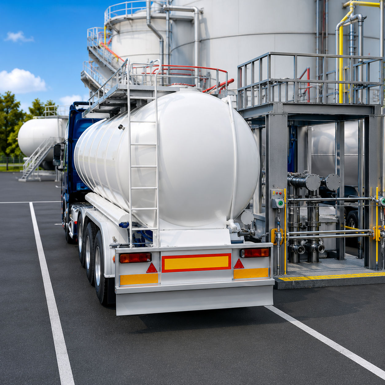
One critical operation susceptible to electrostatic hazards is the loading and unloading of road tankers carrying flammable and combustible products in EX/HAZLOC atmospheres. Such tankers must feature designated grounding points, like an earthing pin, where an electrostatic grounding clamp and cable from the loading gantry can be securely attached. Maintaining electrical continuity between the tanker's chassis, tank, and the designated grounding point, not exceeding 10 Ohms, is a recommended benchmark in both IEC TS 60079-32-1 and NFPA 77. A resistance higher than 10 Ohms can signal issues such as loose or broken connections. Truck manufacturers and fleet operators must ensure that paint coatings do not electrically isolate metal parts from the main body of the tanker, compromising the grounding path.
International Standards for Road Tanker Grounding
- IEC TS 60079-32-1, Section 7.3.2.3.3 'Precautions for road tankers' states:
- a) The bonding resistance between the chassis, the tank, and associated pipes and fittings on the truck should be less than 1 MΩ. For wholly metallic systems, the resistance should be 10 Ω or less. Higher values necessitate investigation for corrosion or loose connections.
- b) An earthing cable must be connected to the truck before any operation (e.g., opening man lids, connecting pipes) and provide a resistance of less than 10 Ω between the truck and the gantry’s designated earthing point. It should remain connected until all operations are completed.
- c) It is recommended that the earth cable in (b) be part of a static earth monitoring system that continuously monitors the truck-to-gantry resistance and activates interlocks to prevent loading if resistance exceeds 10 Ω.
- NFPA 77, Table 12.2, 'Summary of Precautions for Loading Tank Vehicles' states:
- Bonding and Grounding: Tank trucks should be bonded to the fill system, with all bonding and grounding in place before operations begin. Ground indicators, often interlocked with the filling system, are frequently used to verify bonding. Bonding components and fill system continuity should be periodically examined. For top loading, the fill pipe must form a continuous conductive path and contact the bottom of the tank.
Ensuring Effective Grounding with Monitoring Systems
To prevent electrostatic charge accumulation on road tankers, the standard practice involves attaching a grounding clamp to the tanker, connecting it to a designated true earth grounding point. This 'true earth' point must be verified by an electrically competent person to ensure a permanent, low-resistance connection to the general mass of the earth. This connection minimizes the risk of electrostatic charge buildup on the truck, which, if unchecked, could lead to a rapid voltage rise and a static spark discharge. Following recommendations from IEC TS 60079-32-1 and NFPA 77, grounding systems deployed at loading gantries provide a verified connection to the loading rack’s designated grounding point. Such systems typically incorporate a simple GO/NO GO indicator for operators and drivers, confirming when the truck is properly grounded. These systems can also utilize interlocks that respond to a connection resistance of 10 Ohms or less between the truck and the designated grounding point, providing a permissive output to control the product loading/unloading system's flow.
Earth-Rite RTR: Advanced Road Tanker Static Earthing System
The Earth-Rite RTR is a prime example of a road tanker static earthing system engineered to meet the input/output requirements of international standards like IEC TS 60079-32-1, NFPA 77, and API RP 2003.
The system employs an intrinsically safe (ia) AC oscillator circuit to detect if the clamp is correctly connected to the road tanker, based on the tanker's typical capacitance. By completing the circuit through the Earth-Rite RTR’s ground loop cables to the loading rack/gantry’s designated grounding point, the system verifies a connection resistance to true earth of approximately 1000 Ohms or less. While lower resistance is crucial for electrical fault and lightning protection, a resistance up to 1000 Ohms is entirely adequate for safely dissipating static electricity. The Earth-Rite RTR's initial check ensures the true earth ground at the loading rack/gantry is capable of dissipating static charge from the road tanker.
Following this initial check, the Earth-Rite RTR transitions to continuously monitor the resistance of the entire circuit – from the clamp tips attached to the road tanker back to the loading rack/gantry’s designated earth grounding point – ensuring it remains below 10 Ohms, as specified by international standards. This feature, known as Continuous Ground Loop Monitoring (CGLM), guarantees that the static dissipation path from the tanker, via the Earth-Rite RTR, to the designated true earth grounding point is continuously maintained at 10 Ohms or less throughout the entire loading or unloading process. Once these input criteria are satisfied, the Earth-Rite RTR’s three high-intensity GREEN LEDs flash, and its volt-free contacts are energized, enabling control of product loading/unloading and automatically stopping the process if the clamp is accidentally removed or dislodged.
Essential Training for Safe Operations
Operator and driver training on the correct procedure for grounding road tankers is paramount. This fundamental requirement, referenced in IEC TS 60079-32-1 (part (b) of 7.3.2.3.3), emphasizes a 'Clamp on First, Off Last' protocol. This means the road tanker must be grounded before any other operation in the loading/unloading process begins, and the grounding clamp and cable must be the final items removed upon completion. When utilizing grounding systems, providing basic training on their purpose and correct operation is essential for users. To initiate grounding, the driver or operator simply connects the Earth-Rite RTR’s clamp to the road tanker’s designated grounding point. Once the system’s parameters, including a connection resistance of 10 Ohms or less, are met, the LED indicators will switch from fixed red to pulsing green. These attention-grabbing pulsing green LEDs continuously confirm that the grounding system is actively monitoring the resistance from the truck to the loading gantry’s designated grounding point. When the grounding system provides a permissive signal, the driver or operator can safely proceed with subsequent steps in the loading/unloading process. To prevent damage to grounding equipment or potential harm to bystanders, it is critical that the driver or operator removes the grounding clamp and cable only after all operations are complete and prior to the vehicle being moved.
Earth-Rite RTR Certifications
- ATEX (Europe)
- IECEx (International)
- cCSAus (North America)
- CCC (China)
- InMetro (Brazil)
- CCOE (India)
Newson Gale: Leading Hazardous Area Static Grounding Control
For over 40 years, Newson Gale has been at the forefront of hazardous area static grounding control. Their expertise serves industries where processes generating static electricity pose a significant risk of igniting flammable or combustible atmospheres. Newson Gale's range of solutions effectively mitigates static charge accumulation through practical and innovative designs, ensuring robust static control across three key levels.
Newson Gale Static Control Features
- Comprehensive grounding and bonding clamps
- Clear visual verification of grounding status
- Interlockable control systems for process safety
- Clamps equipped with sharpened tungsten carbide teeth, capable of biting through coatings, rust, or product deposits for reliable connection