
The Risk of Electrostatic Charges in Hazardous Areas
Without suitable earthing provisions, electrostatic charges can accumulate on metal containers, such as drums and hazardous area suitable Ex IBCs, during the handling of flammable liquids in hazardous (Ex/HAZLOC) atmospheres.
Once handling operations begin, these metal containers can quickly generate enough voltage for an electrostatic discharge to occur. Such discharges pose risks of ignitions to plant personnel and assets.
Implementing suitable electrostatic earthing and bonding measures is a critical step to mitigating against these risks.
Ensuring Reliable Earthing for Safety
The storage and handling of flammable liquids are necessities for many chemical companies' daily operations. Once a hazardous area classification has been assigned, attention must turn to controlling potential ignition sources.
Risk assessments (e.g., HAZOP analysis) frequently identify electrostatic discharges as a potential ignition source. While best practice guidance like IEC TS 60079-32-1:2013+AMD1:2017 and NFPA 77 provides advice, a common challenge is the earthing of potentially isolated metal plant equipment within a hazardous area.
If metal plant equipment is not suitably earthed prior to handling flammable liquids, electrostatic charges can quickly accumulate once an operation begins, causing voltage levels to increase. When an object reaches a critical 'breakdown voltage', the risk of an electrostatic discharge is present. An ignition can occur if the concentration of flammable gas and/or vapour is within its explosion limits and the discharge energy exceeds the Minimum Ignition Energy (MIE).
The immediate priority is to ensure a local plant earth point, typically a pre-verified earth bar, capable of safely dissipating electrostatic charges. Once verified, all metal plant equipment must share an equipotential bond to this nominated earth point, taking it to 'earth/ground potential'.
Best practice guidance (IEC TS 60079-32-1:2013+AMD1:2017 & NFPA 77 'Recommended Practice on Static Electricity, 2019 Edition') helps establish a repeatable and reliable earth connection. Although ≤ 1 megohm (1 x 10^6 Ω) is generally considered 'adequate' (NFPA 77, 7.4.1.3) for charge dissipation, it should not be confused with a reliable connection for all metal equipment. Both standards conclude that any earth connection exceeding 10 Ω for metal plant equipment can be a sign of 'loose connections or corrosion' requiring further investigation.
Most fixed plant equipment typically has a structural earth connection that can be relied upon if properly maintained and tested. However, ensuring a ≤ 10 Ω earth connection for portable metal containers like drums, hazardous area suitable Ex or stainless-steel IBCs, mixing pans, and buckets can be far more challenging, especially when several portable containers are used simultaneously.
Many users opt for an earthing system that continuously monitors the connection to the designated earth point to mitigate against loose or corroded connections. A system that monitors to a 10 Ω permissive threshold provides continuous indication of a connection that adheres to best practice recommendations.
The Need for Multi-Channel Monitoring
When multiple electrostatic earth monitoring connections are required in a process area, the use of 'traditional' single-channel monitoring systems, each requiring 110/230 V AC power, may not be the most cost-effective or flexible option in terms of installation requirements.
Therefore, the use of a multi-channel earth monitoring system such as the Earth-Rite® MULTIPOINT II should be considered.
This system allows for the simultaneous monitoring of up to eight items of process equipment to a 10 Ω permissive threshold from a single ATEX, IECEx, NEC & CEC certified monitoring control unit, and a 110/230 V AC power supply unit.
Key Features and Advantages of Earth-Rite® MULTIPOINT II
- Monitors to a 10 Ω permissive threshold: Demonstrates compliance with internationally recognized best practice guidance such as IEC TS 60079-32-1 & NFPA 77.
- Continuous Monitoring: Continually monitored connections with visual indication reduce the need for costly and time-consuming electrical continuity checks, which typically require qualified hazardous area specialist personnel who may not always be accessible.
- Application Flexibility: A simple, easy-to-use dipswitch on the monitoring unit PCB allows the user to add/remove channels should their application requirements change.
- Indication Flexibility: Additional remote indicator stations can be positioned local to each monitoring connection, providing the operator with easily accessible indication of a specific channel's current state via red (non-permissive) and green (permissive) LEDs local to each process. This enables a single system to monitor multiple metal containers within a broad plant area.
- Installation Flexibility: The indicator stations are powered by intrinsically safe Ex ia circuits distributed from a single in-line marshalling junction box (supplied with the system). This is advantageous for equipment installers who might otherwise face the prospect of installing several individually powered single-channel systems in an Ex/HAZLOC area. Combining this flexibility with the expected upfront saving of purchasing one multi-channel system over several individual units results in a favorable overall value differential.
- Process Interface Flexibility: Voltage-free contacts located in the power supply unit enable the user to interface with process control devices such as pumps, PLCs, and valves to inhibit their operation until a permissive output is obtained from the corresponding channel(s). Each channel is allocated a single volt-free contact to enable complete segregation between distinct processes. An additional group relay allows for several or all eight channels to be grouped using a simple dipswitch on the power supply unit, ensuring that all grouped channels must be permissive for the group relay to energize. (Note: Process interface/interlock configurations should always be risk assessed by a suitably qualified entity, taking all process parameters into consideration.)
- Reliability: The Earth-Rite® MULTIPOINT II uses secure and reliable software based on the MISRA C protocol. Watchdog circuits located on both the monitoring and power supply units can activate a fail-safe relay also located in the power supply unit.
Case Study: Resin Production Facility
This case study demonstrates how a Newson Gale customer, specializing in the production of resins, improved process safety and efficiency by installing the Earth-Rite® MULTIPOINT II.
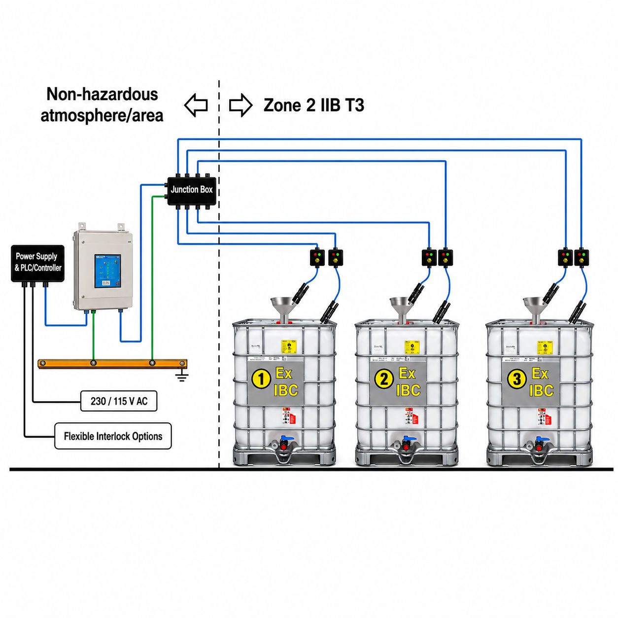
When conducting a HAZOP analysis of its filling area, classified as a Zone 2 IIB T3 gas/vapour atmosphere, the customer identified a requirement to simultaneously monitor three electrostatic protected composite Ex IBCs prior to being filled with a solvent-based resin. The analysis also identified the metal funnels seated on top of the Ex IBCs as potentially isolated conductors requiring an independent monitoring connection. Due to this, a total of six monitoring connections were used.
The operating environment involved a switch room, classified as a non-hazardous area, adjacent to the filling room. The switch room contained the PLC which controlled the hazardous area certified pumps used to drive the flow of material from mixing tanks (structurally earthed) to the Ex IBCs via metal pipework.
The CompEx accredited installer determined the most practical location for installation to be the switch room, positioning the power supply unit, monitoring control unit, and marshalling junction box next to the PLC – the latter two components being terminated to a common pre-verified earth bar.
From there, intrinsically safe Ex ia monitoring circuits were routed via overhead cable trays to remote indicator stations positioned local to each filling station. Finally, two-pole clamps and cable assemblies were specified for each of the Ex IBCs and funnels, with all clamps possessing penetrative tungsten carbide tips to mitigate the potential for viscous product deposits preventing a ≤ 10 Ω connection from being achieved.
Key Benefits from the Case Study Implementation
- The positioning of the monitoring control unit and remote indicator stations provided easily accessible visual indication to operators both inside the potentially hazardous atmosphere and those located remotely in the switch room.
- Interlock control circuit runs were minimized by positioning the power supply unit local to the PLC. The installer grouped the two channels allocated to each filling station in series and interfaced them with the PLC. The PLC was then programmed to ensure that the operation of the inline transfer pump was inhibited until the two channels allocated to that filling station obtained a permissive output. By 'grouping' the channels in this manner, it avoided cross-interference between the respective filling operations at each station, thus outlining the flexibility afforded by the system.
- The two spare channels also 'future-proofed' the equipment against potential operational expansion or changes to process requirements.